Dr. Vadym Zayets
v.zayets(at)gmail.com
My Research and Inventions
click here to see all content |

Dr. Vadym Zayetsv.zayets(at)gmail.com |
|
|
IntroductionExperimental observation of transverse MO effectProperties of transverse MO effectOrigin of transverse MO effectTransverse EllipticityTwo contributions to transverse MO effectMagnetization-dependent optical lossCalculations of transverse MO effect in the case of multilayer structureOptical excitation of spin-polarized electrons utilizing transverse MOPlasmonsGiant Enhancement of Transverse MO effectHistory and Future |
Transverse Magneto-Optical effect
Two Contributions to Transverse MO effectIn contrast to longitudinal MO effect, the transverse MO has two contributions. The first contribution comes from a bulk of MO material and the second contribution comes from the interface. These two contributions are often of opposite sign and about the same magnitude. Often they compensate each other and it causes a weak transverse MO effect. However, if these two contributions are optimized (for example by optimizing the device structure), the transverse MO may be significant and in some cases it can be very large.Simple modelTwo contributions for the transverse effect can be always estimated or calculated. The following method might be simple, but it can give a quick rough estimation for the values of both contributions. Let us calculate the transverse MO effect of a very general structure, which consists of the ferromagnetic metal and transparent dielectric. Both the dielectric and the may consists of many layers. The light propagates along the metal. The metal absorbs the light and there is MO effect in the metal. We would like to calculate how much optical loss changes when the magnetization of the metal is reversed. Both absorption coefficient k and refractive index of ferromagnetic metal is different for two opposite magnetization directions. Since refractive index of metal is magnetization-dependent, the refractivity of at interface between the metal and the dielectric is different for opposite magnetization directions. Therefore, amount of light inside the metal changes with magnetization reversal. In other words, with magnetization reversal the optical field is displaced so that there is more or less optical field inside the metal. The optical loss is proportional to both the absorption coefficient of the metal and the amount of light inside the metal. For two opposite directions of magnetization the absorption coefficient of the metal and amount of light inside the metal are expressed as
Magnetization-dependent optical loss is
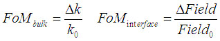
MO figure-of-merit is a ratio of magnetization-dependent optical loss to average optical loss
where
MO Figure-of-Merit for the bulk and interface contributions , respectively. The bulk contribution describes the change of optical absorption of the material itself (of the ferromagnetic metal in our case). The interface contribution describes the displacement of optical field (in or out of the ferromagnetic metal)
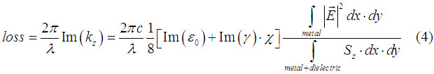
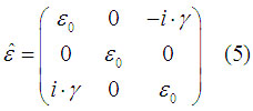
Detail ModelThe values of the two contributions may be calculated more precisely using expression for magnetization dependent loss.( which is derived here) Again we calculate the transverse MO effect of very general structure, which consists of the ferromagnetic metal and transparent dielectric. Both the dielectric and the may consists of many layers. The expression,which described the optical loss for this very general structure is (Expression (14) here)
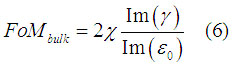
where is the permittivity tensor of the ferromagnetic metal, S is Poynting vector and ksi is the transverse ellipticity of light. When the magnetic field is reversed, the absorption of light changes, because of the transverse MO effect. In Exp. (4) only two values depend on the polarity of the magnetic field. The off-dioganal element of permittivity tensor gamma changes sign and the optical field distribution is changed when the magnetic field is reversed. If we assume that the distribution of an optical field does not depend on the magnetic field, the ratio of integrals at the left part of (4) would be the same for both directions. That assumption means that the redistribution of the optical field due to the influence of the interface is ignored. Than, FoM of the bulk contribution to transverse MO effect is derived from (4) as
The FoM of the bulk contribution is linearly proportional to the transverse ellipticity. It supports explanation of the origin of the transverse MO effect. Also, it is linearly proportional to off-diagonal element of permittivity tensor. That proves that transverse MO effect is linear MO effect. It should be considered that optical field distribution near the interface depends on the refractive index of both the metal and the dielectric. In the case of non-zero transverse ellipticity the effective refractive index of the metal changes with reversal of the magnetic field due to MO effect. That leads to the redistribution of the optical field near the interface and the ratio of integrals at the left part of (4) will be different for opposite directions of the magnetic field. That defines the interface contribution to the transverse MO effect. The interface contribution is explained as follows. The MO change of the effective refractive index of the metal redistributes relative amounts of light energy between the dielectric and the metal. Since the absorption by the metal is proportional to the amount of light inside it and this amount changes with reversal of the magnetic field, the optical loss of the wave will also change with the reversal of the magnetic field.
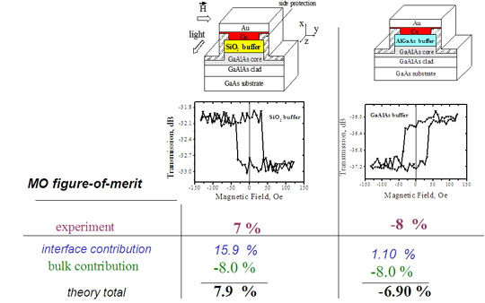
Hybrid waveguidesThe following is an excellent example showing the importance of two contributions for transverse MO effect. In this example the magnetization-dependent loss was experimentally measured in a ferromagnetic-metal/semiconductor optical waveguide. A tiny change in device structure causes significant changes in value of transverse MO effect. Two practically identical AlGaAs:Co hybrid waveguides were fabricated. Only the material of buffer layer between Co and the waveguide was different. The magnetization-dependent loss was measured for both waveguides. Surprisingly, even there is only such slight difference in the structure; the polarity of magnetization-dependent loss was different for these waveguides. The difference is because the bulk contribution is the same in both cases, but interface contribution is of opposite signs and it is negligible in the case of Co:AlGaAs interface and is about two times greater than the bulk contribution in the case of a Co:SiO2 interface. SiO2 has relatively small refractive index, but AlGaAs has relatively large refractive index. The refractive index of layer between Co and the waveguides greatly influence the interface contribution, but almost does not affect the bulk contribution. For more detail explanations about my experiments with hybrid waveguides, click here.
|
I will try to answer your questions as soon as possible